
1. Purpose of the article
- This article will guide you how to connect and basic configuration on Netgear ProSafe JGS524PE switch using NetSA ProSAFE Plus Configuration v2.7.7 software.
2.Configuration
a. How to connect to the admin page
- You can connect to the administration page with the device’s ip using a web browser or connect with its own software, ProSAFE Plus Configuration v2.7.7 (Click to download).
- After downloading the software and installing, you need to connect the network cable to the switch and open the software to scan the switch’s address.
- Note that the IP address of the computer on which you install the software is displayed in the Located on IP Network column, which must be the same network layer as the switch’s IP Address.
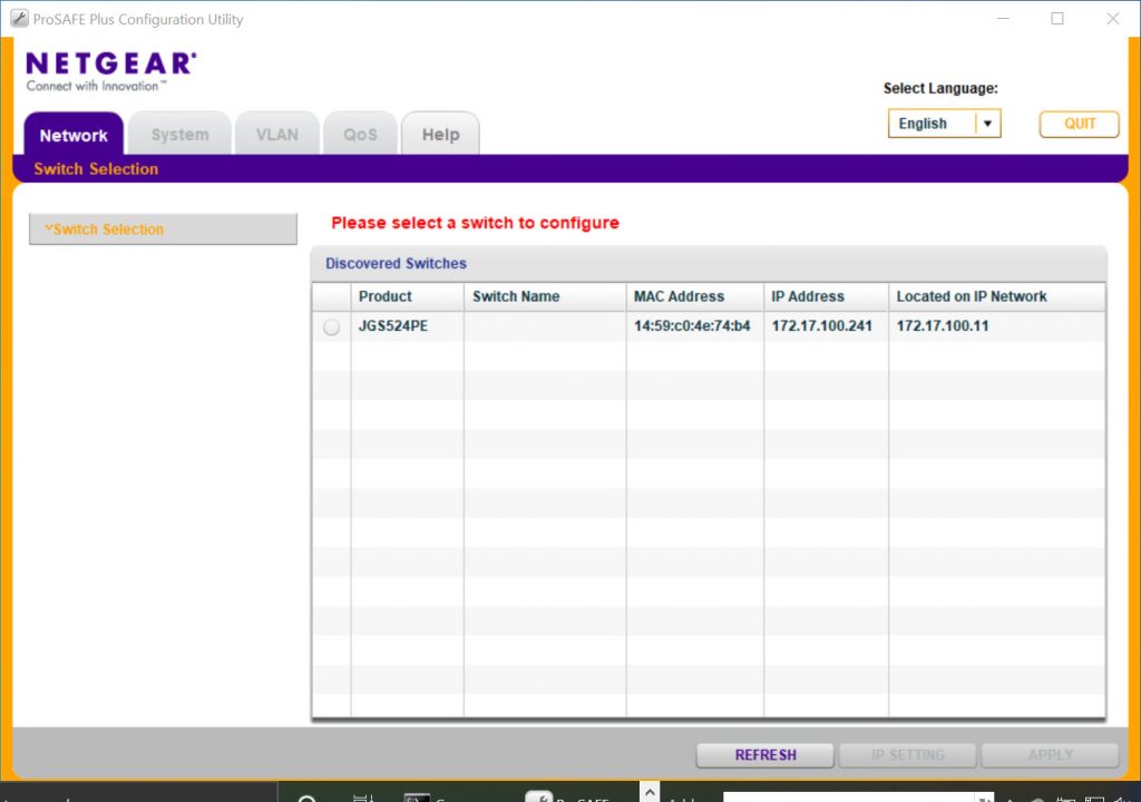
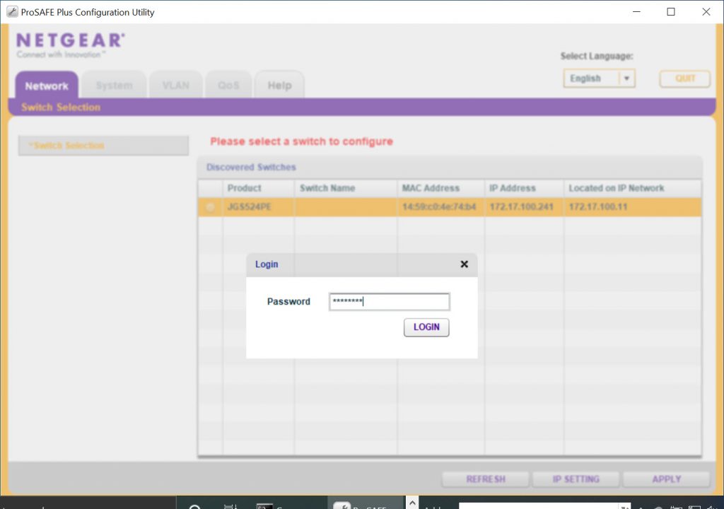
- Click on the scanned result, select Apply and enter the password of the switch to login (the default password of the switch is ‘password’).
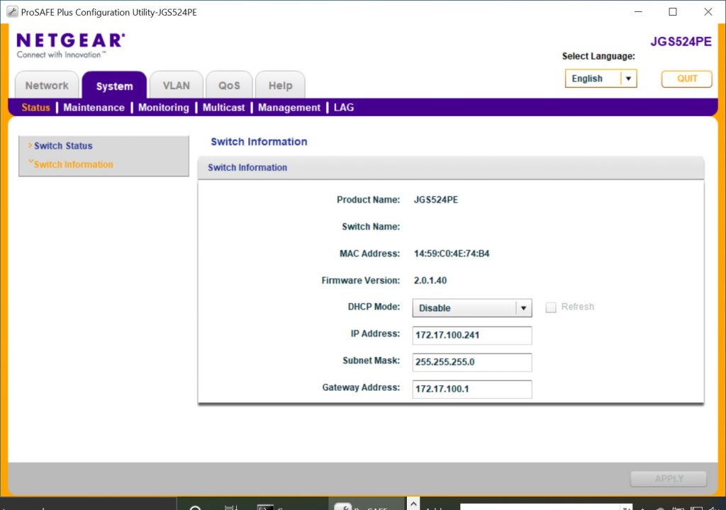
b. How to change the IP for the switch
- To change the IP address of a switch, go to System> Status> Switch information to change the IP.
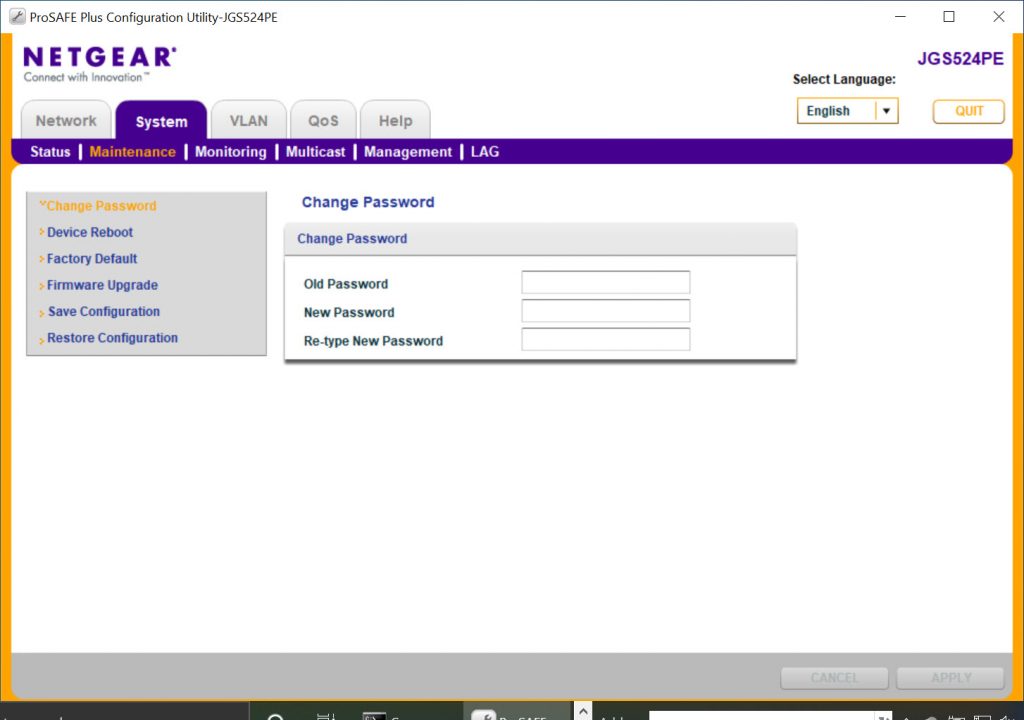
c. How to change the password for the switch
- Để đổi mật khẩu cho switch các bạn vào System > Maintenance > Change Password để đổi.
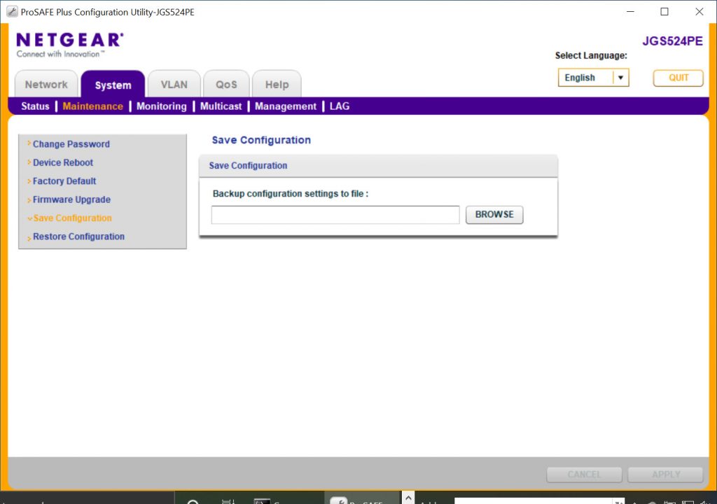
d. How to save backup configuration
- To backup the configuration of your switch go to System> Maintenance> Save Configuration, on the right you click BROWSE and choose where to save the backup file and click Apply.
e. How to configure VLAN
- In this section we assume to receive a request for customers’ vlan configuration as follows.
- Customer requests from port 1 to port 12 will be on vlan 180 and port 13 to port 22 will be on vlan 100, 2 port 23, 24 will be 2 port trunking.
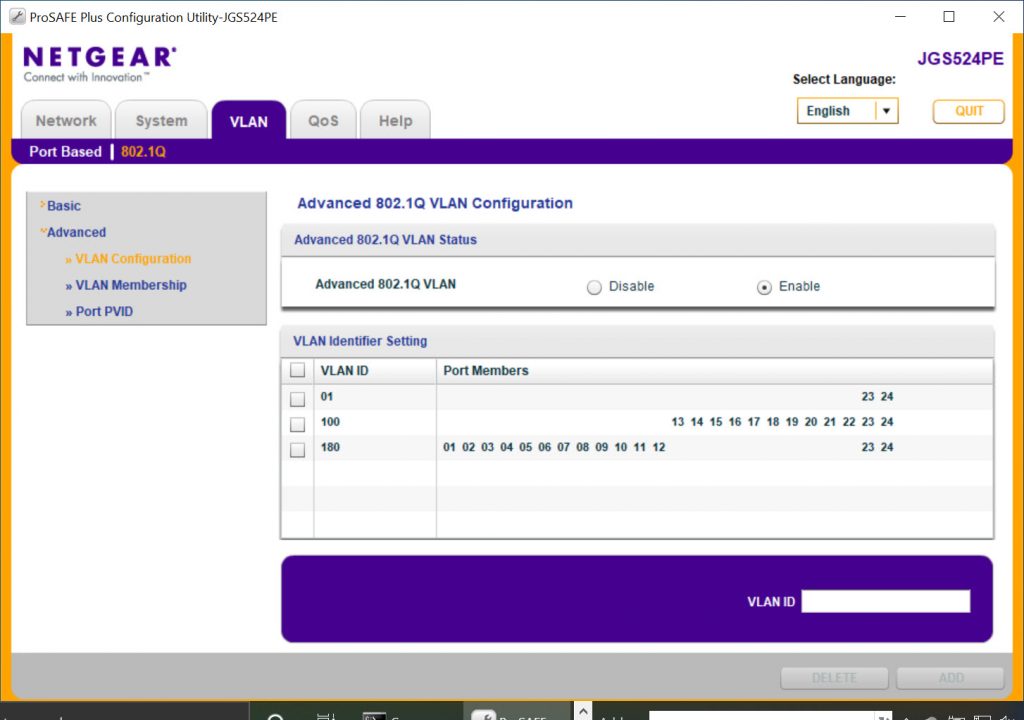
- To configure us go to VLAN> 802.1Q> Advanced> Advanced 802.1Q VLAN> Enable.
- By default this time only vlan 1 and all ports will be in vlan 1.
- To create a vlan, click on the VLAN Configuration and enter the VLAN ID we want to create into the free space on the right of the VLAN ID and then click Apply to save.
- As required above we will create 2 vlan 100 and 180.
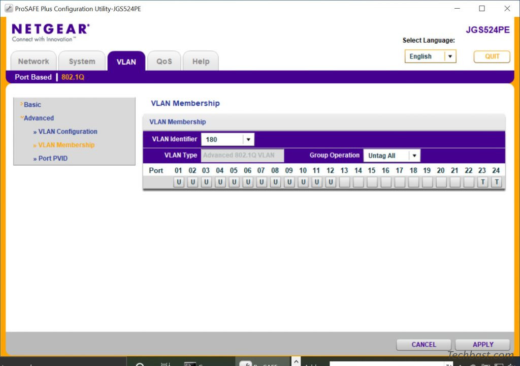
- Next we will assign port to vlan as required above.
- To perform click VLAN Membership.
- We will assign port 1 to port 12 into vlan 180 by selecting vlan 180 in the VLAN Identifier and checking U (Untag) to position the empty cells below the port number.
- Since 2 ports 23 and 24 are 2 trunk ports, we will tick the T (Tag) for these 2 ports in VLAN 180
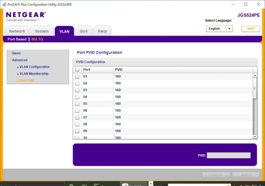
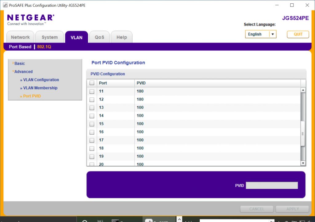
- Next we need to configure the PVID for ports 1 to 12 (the default PVID of the ports is 1 to match the VLAN ID).
- To configure our PVID, go to the Port of PVID, select the ports we want to change the PVID, enter the number of PVID we want (PVID always matches the VLAN ID) into the box and click Apply.
- Back to VLAN Membership, now that ports 1 to 12 belong to 2 vlan 1 and 180, we will select vlan 1 at VLAN Identifier and remove the U (Untag) symbols at the bottom of the ports 1 to 12 in vlan 1.
- Click Apply to save.

- We also do the same steps for ports 13 through 22 for VLAN 100.
Leave a Reply