
1.Purpose of the article
This article describes the steps to configure multiple IPsec VPN connections for redundancy. If the primary VPN link doesn’t work, the backup Internet VPN link takes its place.
2.Network diagram
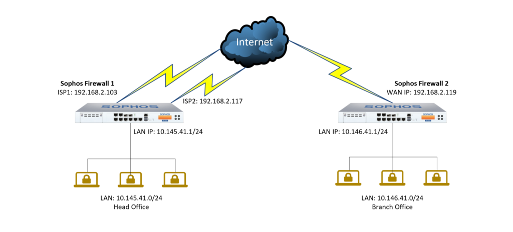
Network diagram details:
Sophos Firewall 1 (SF1) appliance
- On a device with 2 internet lines, ISP 1 has IP 192.168.2.103 configured at Port 2 and ISP 2 has IP 192.168.2.117 configured at Port 3.
- The LAN layer is configured at Port 1 with IP 10.145.41.1/24 and has DHCP configured to allocate devices to connected devices.
Sophos Firewall 2(SF2) appliance
- On the device, there is an internet line with IP 192.168.2.119 configured at Port 2.
- The LAN layer is configured at Port 1 with IP 10.146.41.1/24 and has DHCP configured to allocate to connected devices.
3.Configuration situation
We will configure 2 IPSec Site to site VPN connections from Sophos Firewall 1 device to Sophos Firewall 2 using 2 ISP 1 and ISP2 lines..
After that, the IPSec failover configuration will be performed so that when the IPSec VPN connection with ISP 1 has a problem, the IPSec VPN connection with ISP 2 will be replaced.
4.Configuration steps
Configuration on Sophos Firewall 1:
- Create profiles for the local and remote LAN network layers.
- Create an IPSec VPN connection using ISP 1.
- Create an IPSec VPN connection using ISP 2.
- Add 2 firewall rules to allow VPN traffic.
- Open 2 HTTPS and PING services for VPN zone.
Configuration on Sophos Firewall 2:
- Create profiles for the local and remote LAN network layers.
- Create an IPSec VPN connection to ISP 1.
- Create an IPSec VPN connection to ISP 2.
- Configure Failover for IPSec VPN connections.
- Add 2 firewall rules to allow VPN traffic.
- Open 2 HTTPS and PING services for VPN zone.
Check the result.
5.Configuration guide
5.1.Configuration on Sophos Firewall 1
5.1.1.Create profiles for the local and remote LAN network layers.
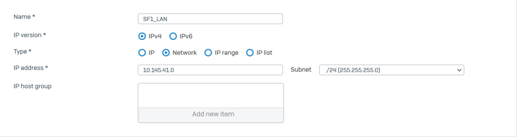
Click Hosts and Services > IP Host and click Add to create a local LAN with the following parameters:
- Name*: SF1_LAN.
- IP version*: IPv4.
- Type*: Network
- IP address*: 10.145.41.0 – Subnet /24[255.255.255.0].
- Click Save.
Click Hosts and Services > IP Host and click Add to create a remote LAN with the following parameters:
- Name*: SF2_LAN.
- IP version*: IPv4.
- Type*: Network
- IP address*: 10.146.41.0 – Subnet /24[255.255.255.0].
- Click Save.

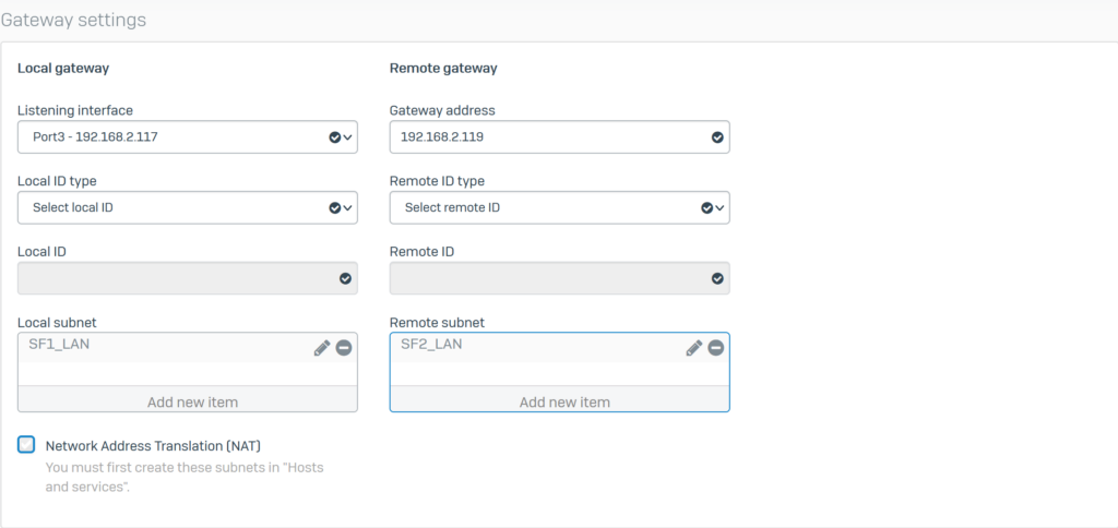
5.1.2.Create an IPsec VPN connection using ISP 1
Click VPN > IPsec Connection and click Add. Create an IPsec VPN connection with the parameters as shown below and use the IPS1 port as Listening Interface.
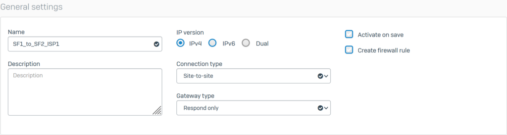
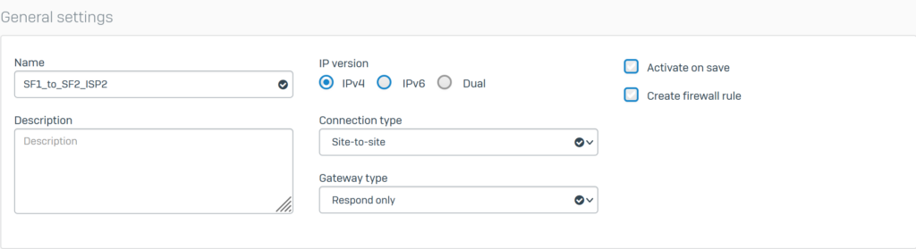
Configure General settings with the following parameters:
- Name: SF1_to_SF2_ISP1.
- IP version: select IPv4.
- Connection type: select Site-to-site.
- Gateway type: Respond only.
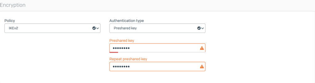
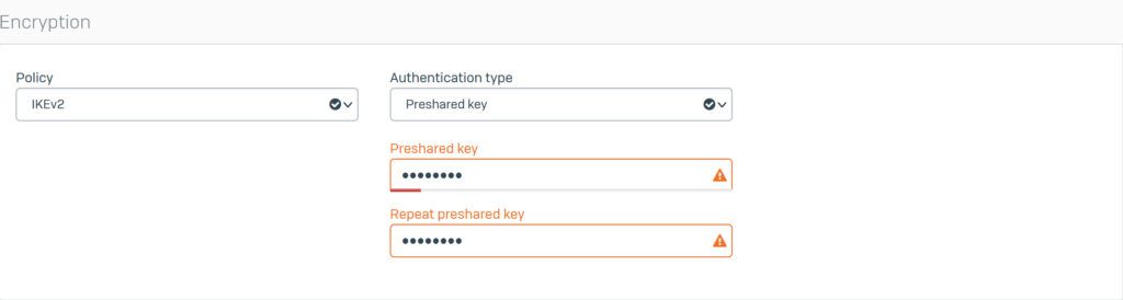
Configure Encryption with the following parameters:
- Policy: select IKEv2
- Authentication type: select Preshared key
- Enter the password in the 2 boxes Preshared key and Repeat preshared key
Configure General settings with the following parameters:
- Listening interface: select Port2 – 192.168.2.103.
- Gateway address: enter SF2’s WAN IP as 192.168.2.119.
- Local subnet: select the SF1_LAN profile.
- Remote subnet: select the SF2_LAN profile
- Click Save to save.
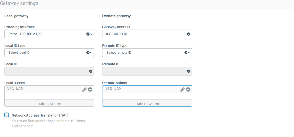
5.1.3.Create an IPSec VPN connection using ISP 2.
Create another IPsec connection using the information as shown below and use the ISP2 port as Listening Interface.
Configure General settings with the following parameters:
- Name: SF1_to_SF2_ISP2.
- IP version: select IPv4.
- Connection type: select Site-to-site.
- Gateway type: select Respond only.
Configure Encryption with the following parameters:
- Policy: select IKEv2.
- Authentication type: select Preshared key.
- Enter the password in the 2 boxes Preshared key and Repeat preshared key
Configure Gateway settings with the following parameters:
- Listening interface: select Port3 – 192.168.2.117.
- Gateway address: enter SF2’s WAN IP as 192.168.2.119.
- Local subnet: select the SF1_LAN profile
- Remote subnet: select the SF2_LAN profile
- Click Save.
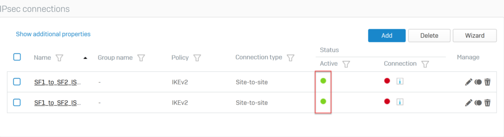
The two newly created IPsec VPN connections will appear as follows.
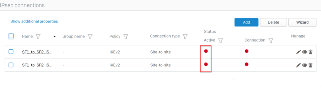
Click the red circle icon in the Status Active column to enable these 2 VPN connections.
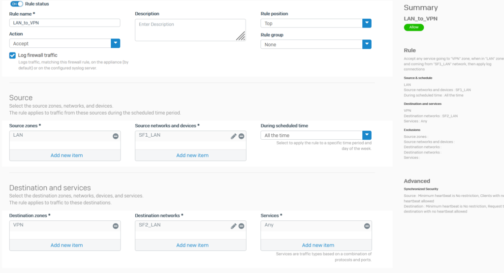
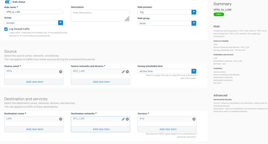
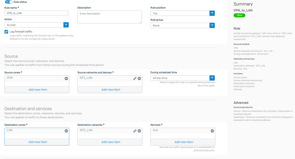
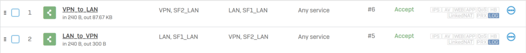
5.1.4.Add 2 firewall rules to allow VPN traffic
Click Rules and policies > Add Firewall Rule > New firewall rule. Create 2 firewall rules as shown below..
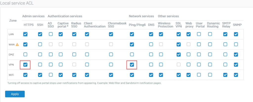
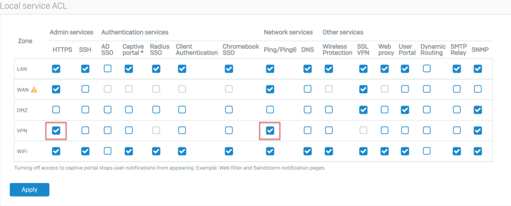
5.1.5.Open 2 HTTPS and PING services for VPN zone.
To be able to ping between hosts of 2 devices SF1 and SF1 through IPSec VPN, we need to open 2 HTTPS and PING services on VPN zone.
To open go to Administration > Device Access.
Select HTTPS and PING services for VPN zone and click Apply to save.
5.2.Configuration on Sophos Firewall 2
5.2.1.Create profiles for local and remote LAN network layers
Click Hosts and Services > IP Host and click Add to create a local LAN with the following parameters:
- Name*: SF1_LAN.
- IP version*: IPv4.
- Type*: Network
- IP address*: 10.145.41.0 – Subnet /24[255.255.255.0].
- Click Save.
Click Hosts and Services > IP Host and click Add to create a remote LAN with the following parameters:
- Name*: SF2_LAN.
- IP version*: IPv4.
- Type*: Network
- IP address*: 10.146.41.0 – Subnet /24[255.255.255.0].
- Click Save.
5.2.2.Create an IPsec VPN connection to ISP 1
Click VPN > IPsec Connection and click Add. Create an IPsec VPN connection using the parameters below.
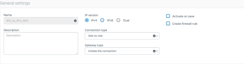
Configure General settings with the following parameters:
- Name: SF2_to_SF1_ISP1.
- IP version: select IPv4.
- Connection type: select Site-to-site.
- Gateway type: Initiate the connection.
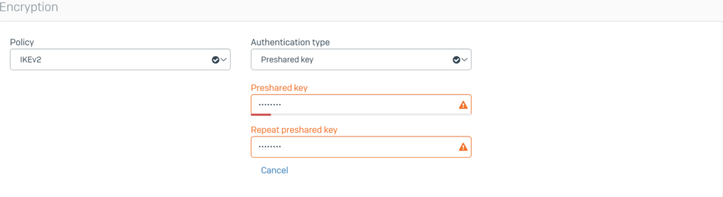
Configure Encryption with the following parameters:
- Policy: select IKEv2
- Authentication type: select Preshared key
- Enter the password in the 2 boxes Preshared key and Repeat preshared key (enter the same password as entered on SF1).
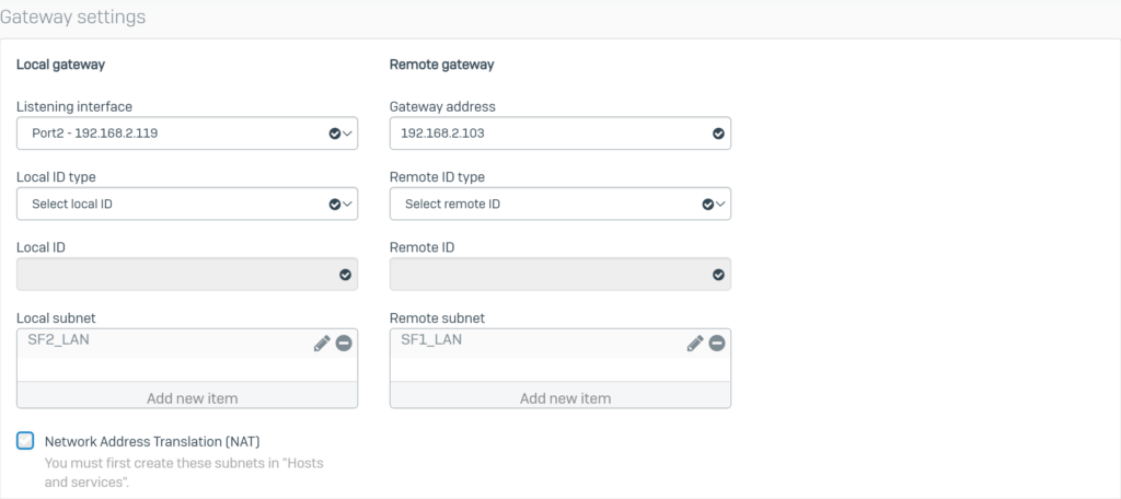
Configure Gateway settings with the following parameters:
- Listening interface: select Port2 – 192.168.2.119.
- Gateway address: Enter the WAN IP (ISP 1) of SF1 as 192.168.2.103.
- Local subnet: select the SF2_LAN profile.
- Remote subnet: select the SF1_LAN profile.
- Click Save to save.
5.2.3.Create an IPSec VPN connection to ISP 2.
Create another IPsec connection using the information below.
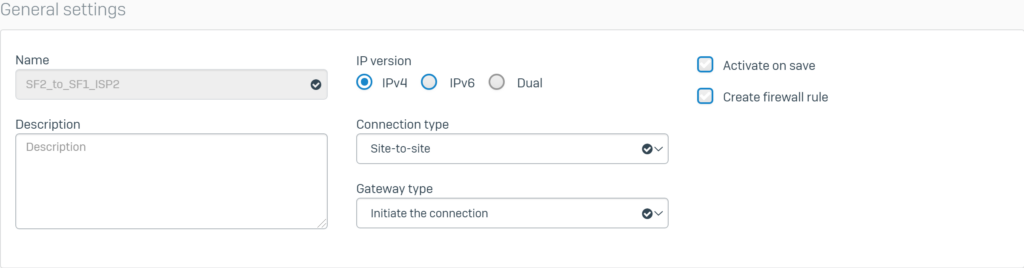
Configure General settings with the following parameters:
- Name: SF2_to_SF1_ISP2.
- IP version: select IPv4.
- Connection type: select Site-to-site.
- Gateway type: select Initiate the connection.
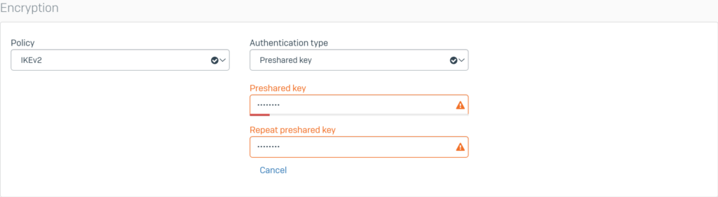
Configure Encryption with the following parameters:
- Policy: select IKEv2.
- Authentication type: select Preshared key.
- Enter the password in the 2 boxes Preshared key and Repeat preshared key (enter the same as in SF1).
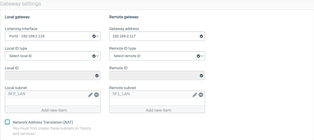
Configure Gateway settings with the following parameters:
- Listening interface: select Port3 – 192.168.2.119.
- Gateway address: enter SF1’s WAN IP (ISP 2) as 192.168.2.117.
- Local subnet: select the SF2_LAN profile.
- Remote subnet: select the SF1_LAN profile.
- Click Save.
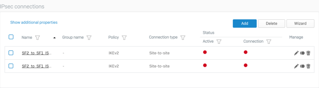
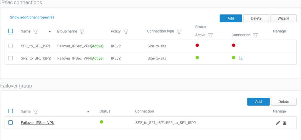
The two newly created IPsec VPN connections will appear as follows.
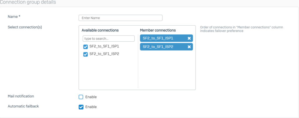
5.2.4.Configure Failover for IPSec VPN connections.
Below the Failover Group section, click Add.
Configure Failover according to the following parameters and click Save.
The following screen will be displayed for the Failover Group section.
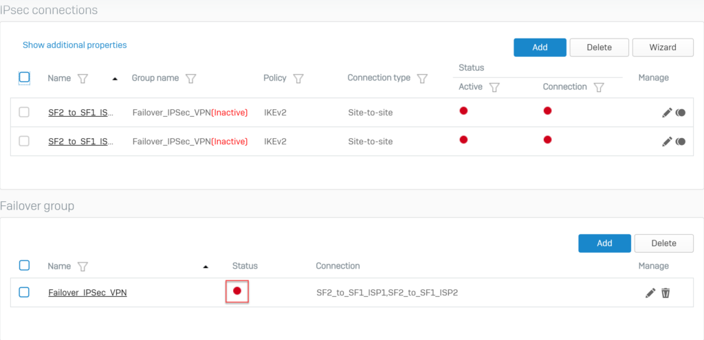
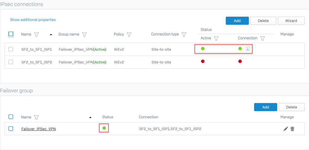
Click on the red circle icon below the Status of the Failover Group that has been created to activate and establish the primary connection.
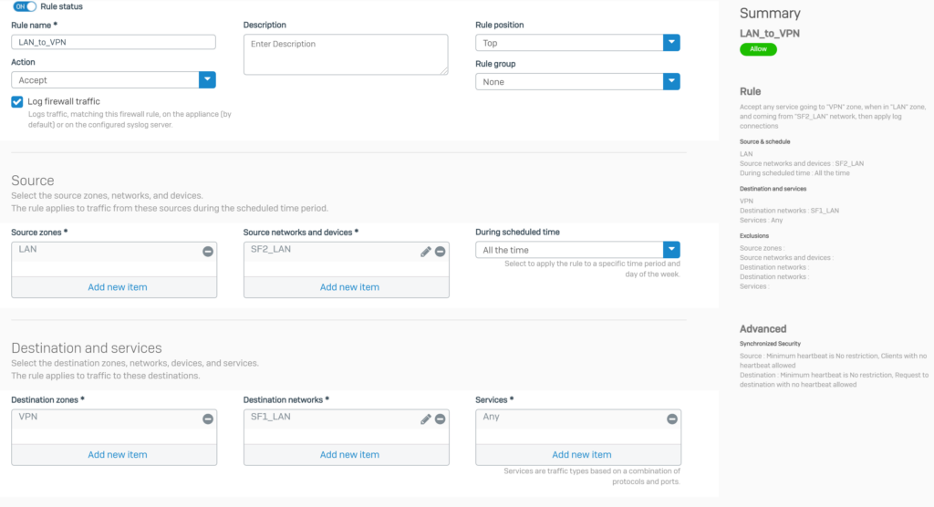
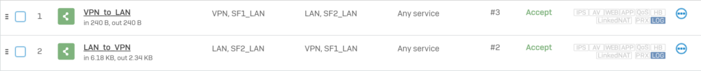
5.2.5.Add 2 firewall rules to allow VPN traffic
Click Rules and policies > Add Firewall Rule > New firewall rule. Create 2 firewall rules as shown below.
5.1.5. Open 2 HTTPS and PING services for VPN zone.
To be able to ping between the hosts of two devices SF1 and SF2 through IPSec VPN, we need to open HTTPS and PING services on the VPN zone.
To open go to Administration > Device Access.
Select HTTPS and PING services for VPN zone and click Apply to save.
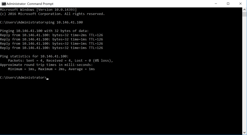
5.3.Check result.
Using a SF1 LAN class machine with IP 10,145.41.11 and pinging a SF2 LAN class machine with IP 10.146.41.100 and the result is a successful ping.
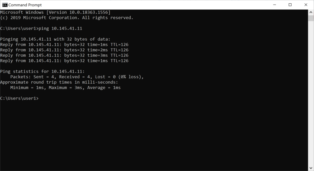
Do the reverse ping from the machine with IP 10.146.41.100 to the machine with IP 10.145.41.11 and the result is a successful ping.
Visit the list of firewall rules on both SF1 and SF2 to verify that the firewall rule VPNs allow inbound and outbound traffic.
On SF1.
On SF2.
Go to Report > VPN and verify the IPsec traffic.
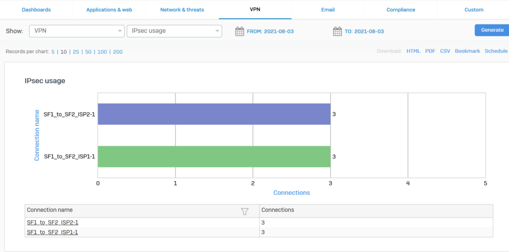
Whenever the ISP Internet VPN 1 link is down, the IPsec connection switches to the VPN Internet ISP 2 link.
We will try disconnecting the VPN connection of the ISP1 line and we will see that the VPN connection of the ISP line 2 will automatically take over.
Leave a Reply