
Overview
- This article provides information about Local Service ACL (Access Control List) and how it works on the Sophos XG Firewall.
Introducing Local Service ACL
- Local Service ACL is located in Administrator > Device Acces. The device carries a default ACL when connected and powered on for the first time. Details of the default services and ports are shown below. Click to turn on or turn off access to services from the designated areas and then click Apply.
| Zone | Service |
| Admin Services | |
| LAN WiFi | HTTPS (TCP Port 4444) Telnet (TCP port 23) SSH (TCP port 22) |
| WAN | HTTPS (TCP port 443) Telnet (TCP port 23) SSH (TCP port 22) |
| Authentication Services | |
| LAN WiFi | Client Authentication (UDP port 6060) Captive Portal Authentication (TCP port 8090) RADIUS SSO |
| Network Services | |
| LAN WAN WiFi | Ping/Ping6 DNS |
| Other Services | |
| LAN WiFi | Wireless Protection Web Proxy SMTP Relay |
| LAN WAN DMZ WiFi | SSL VPN (TCP port 8443) |
| LAN WAN | User Portal Dynamic Routing |
| LAN DMZ VPN WiFi | SMNP |
- Note: User authentication services are required in order to apply user-based Internet surfing, bandwidth, and data transfer restrictions. These are not required for administrative functions.
- The following are the default configuration of the Local Service ACL.
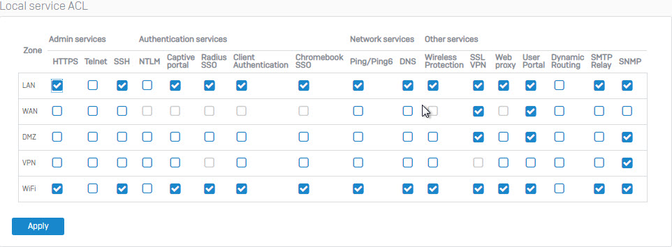
- Local Service ACL allows or denies access to specified services in a zone.
- For example, by default, Ping / Ping6 is disabled for the WAN area. A user from the internet tries to ping Sophos XG Firewall’s WAN IP. Because the Ping / Ping6 service is disabled for the WAN area, the packets will be dropped and therefore ping will fail.
- Another example is for Dynamic Routing. By default, Dynamic Routing is disabled for all regions. Consider the following issue.
- The following is a diagram of configuring dynamic RIP routing between two WAN ports of two XG firewall devices, FW1 and FW2.

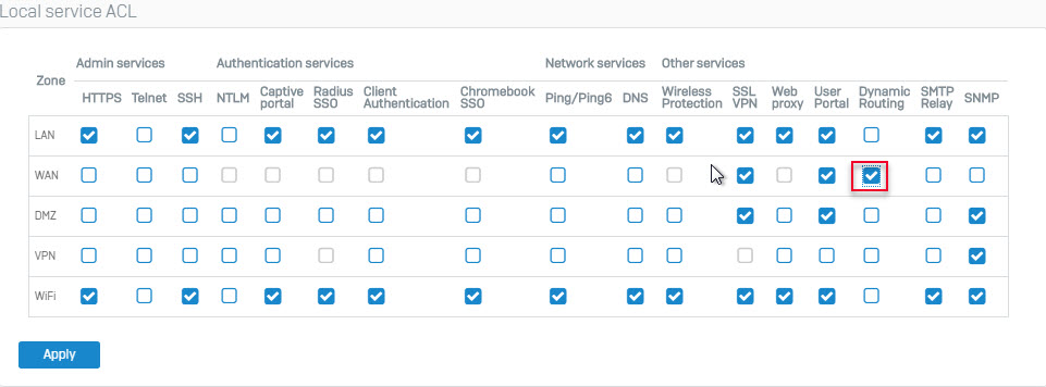
- First we log into the admin page of FW1 using the LAN port with the link https://172.16.16.164444 and click Administrator> Device Access to access the Local Service ACL.
- Check the Dynamic Routing box in the WAN area and click Apply to enable it for the WAN area.
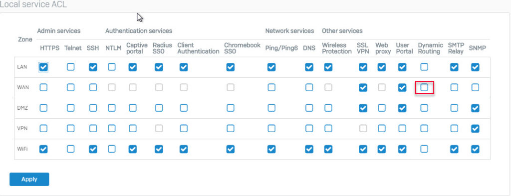
- Next we log into the admin page of FW1 with the LAN port with the link https://172.16.17.16:4444 (changed LAN address during installation) and click Administrator> Device Access to access the Local Service ACL.
- We see that Dynamic Routing is still not enabled for WAN port, we keep this configuration.
- At this point in the Local Service ACL configuration of the two firewall device. Dynamic Routing turned on for the WAN area in FW1 and Dynamic Routing turned off for the WAN area at FW2.
- Next we will configure RIP routing for both FW1 and FW2 devices.
- You can see the instructions here.
- After configuring RIP routing, RIP updates are configured to be sent across WAN areas of both firewalls. Because XG1 is enabled Dynamic Routing for WAN area, XG1 will receive RIP updates from XG2. RIP updates that XG1 is sending to XG2 will be canceled because XG2 is disabled Dynamic Dynamic Routing for WAN area.
- Therefore, in the routing table, XG1 will display the networks promoted by XG2 (172.16.17.0/24 network layer) but XG2 will not display the networks promoted by XG1 (network layer 172.16.16.0/24) . We click Routing> Information to enter the routing table of both devices.
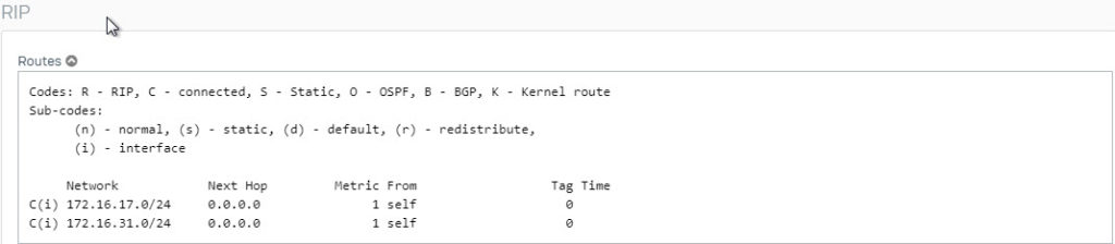
FW1 routing table
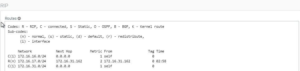
- As you can see, the routing table of FW1 with 172.16.17.0/24 network is updated from FW2 via RIP routing.
FW2 routing table
- As you can see, the routing table of FW2 does not receive the 172.16.16.0 network layer from FW1 since we have not enabled Dynamic Routing for the WAN area on FW2.
Introducing the Local Service ACL Exception Rule
- Use the Local Service ACL Exception Rule to allow access to device administrator services from a designated network / server.
- To create this rule, click Administrator > Device Access. Under the Local Service ACL Exception Rule click Add to add the rule.
- For example, here we will create a rule that prohibits users from the 172.16.16.0/24 network layer in the LAN area to connect SSH to the firewall device using the LAN (port 1) on the firewall device.
- We need to fill in the information as shown below.
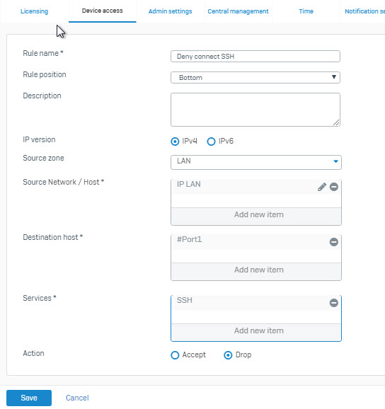
- Rule Name: Name the rule.
- Rule Position: Select the location for the rule.
- Description: Enter the description for the rule.
- IP Version: Supports both IPv4 and IPv6, in this example choose IPv4.
- Source zone: Select an arbitrary zone, in this example choose LAN Zone.
- Source Network / Host *: Click Add new item to select the source host (based on the network layer, IP address or list) that this rule will apply. Click Create New to create a new source host. In this example, I will click Add new item> Create New> Network. A table appears, enter the name in the Name of IP LAN field, select Network and enter IP address in the IP address box. The IP address in this example is 172.16.16.0 and Subnet is / 24.
- Destination host *: Select # Port1 because this port is a LAN port and for example we will ban users from connecting SSH from the IP address of this port.
- Service *: click Add new item and select SSH.
- Action: select Accept to allow and select Drop to ban, here will select Drop.
- Click Save.
- Then access the LAN user computer with the IP address of the 172.16.16.0/24 network layer and make an SSH connection to the firewall device with the LAN port address as 172.16.16.16 using the PuTTy application and we will see that access is denied.
Leave a Reply